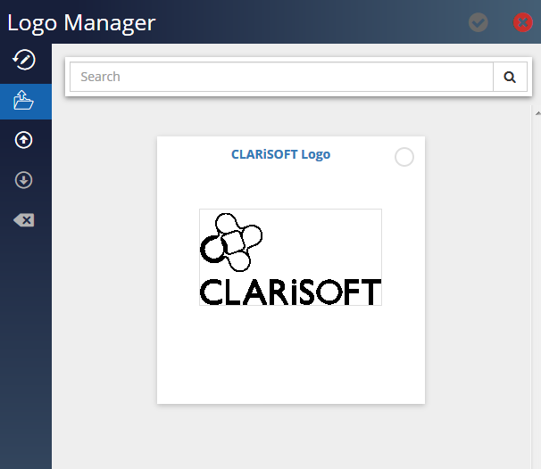
Logo Manager allows the user to view and manage the logos uploaded to Design folder.
Advanced Job for Secondary Packaging
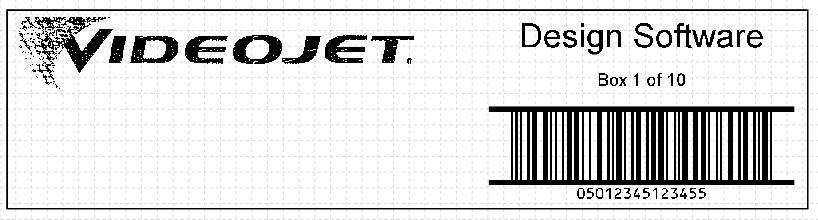
This example describes the steps required to build a typical carton / secondary packaging job and introduces new tools / fields: Logos and Drawings.
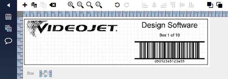
An example of the completed image:
Define Target Printer
| 1. | Start a new job in Design and select printer model Videojet 236x and variant 500. The Videojet 236x is a Large Character Marking (LCM) printer ideally suited for printing directly onto shipping cartons. |
| 2. | Select the New Blank Template from the job list and click Edit. Enter the job name Secondary with Logo and start editing the job. |
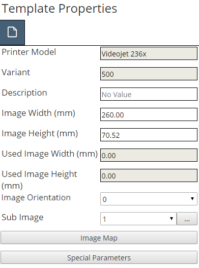
| 3. | From the template properties window, set the image width to 260mm and leave the height at 70.52mm (the maximum print height for the Videojet 236x print head). |
Insert a Logo
| 4. | Click + on the toolbar from the job editor page (see Figure 4-4 on page 4‑2). |
| 5. | Click on the Logo tool in the Toolbox and enter the field name ‘Videojet’ in the window. Click ✓ to close the window. A sample logo is placed at the selected location and the Logo Properties window appears. |
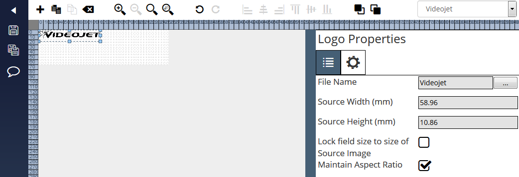
| 6. | For this example move the logo approximately at coordinates 5, 5 (millimetres across and down from the top left corner of the image design area). |
| 7. | Select the file name ‘Videojet’ in Logo Properties tab to open Logo Manager window. |
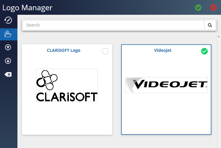
| 8. | Select the file and click ✓ to insert the selected graphic to the image design area. Ensure the Maintain Aspect Ratio is enabled and drag the logo to increase the size of the logo. |
Note: Design works only with monochrome logos and will automatically convert colour sources files if required.
![]()
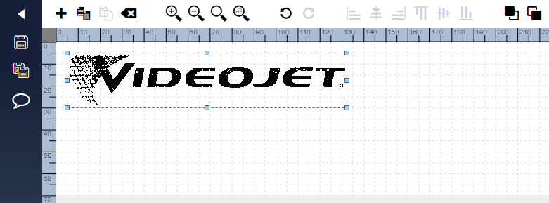
| 9. | The logo is too big to entirely fit in the image design area. If Design cannot print an object correctly, it changes its colour from black to red. This occurs if the object is partially (or fully) off the image design area or if the object overlaps with another object or the target printer cannot support overlapped fields. Resize the logo by dragging the bottom right corner (indicated with a small, blue square) diagonally up to the left. Reduce the size so that the bottom of the logo is approximately 5mm above the bottom of the image design area as seen in the following screenshot: |
Insert a Shape
| 10. | In the finished image, there is a rectangular box around its perimeter; this is added using the Shape tool. Click on the Shape tool in the Toolbox and enter the field name ‘Rectangle’ in the window. The default drawing shape (Shape) is added to the image design area which is the required Outline Box and Shape properties window appears. |
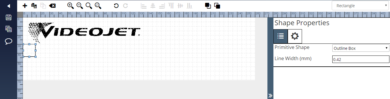
| 11. | The inserted outline box is not big enough; drag the bottom, right corner of the box (as highlighted with a small, blue square) until the box is approximately 3mm from all edges of the image design area. Objects can be selected by clicking on them. |
Inserting a Barcode
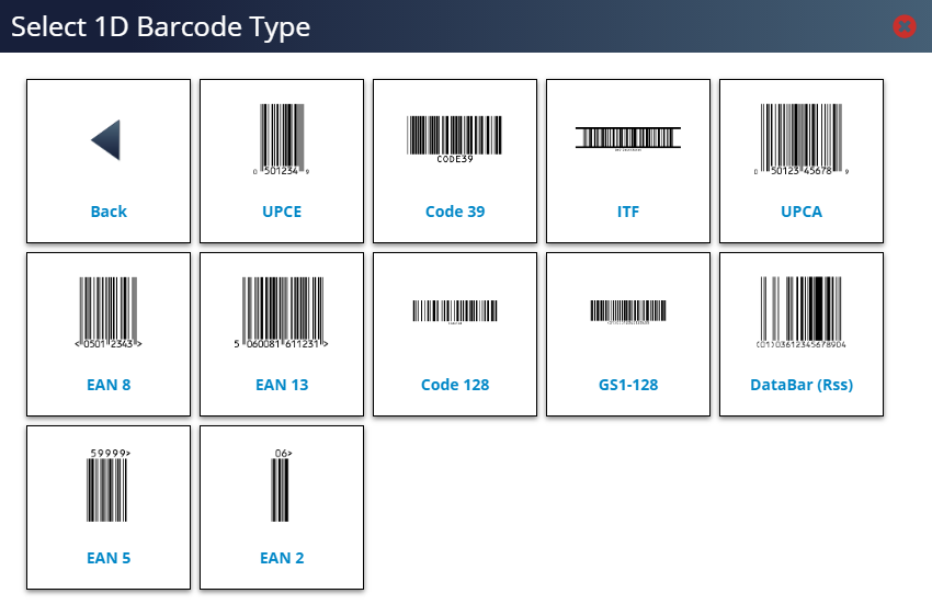
| 12. | For this example include an ITF barcode; a 14 digit Global Trade Item Number (GTIN) commonly used on secondary packaging. Click on 1D Barcode in the Toolbox and then click on ITF. |
| 13. | Enter the field name ‘bcITF’ in the window and click X to close the window. The ITF barcode is added to the image design area and display the ITF Properties window. Design places a default value in the Data field. Enter a 14 digit numeric value in this field (Design allow longer or shorter lengths but there must always be an even number of digits). |
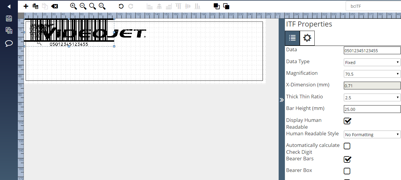
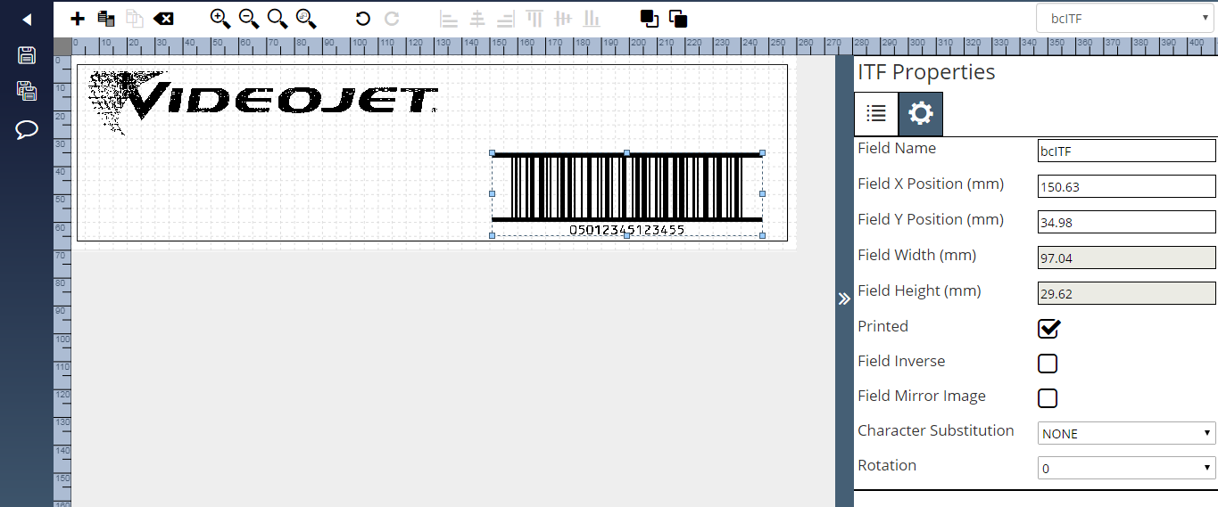
| 14. | For this example move the barcode to 150, 35 using the coordinates in the ITF properties General tab. |
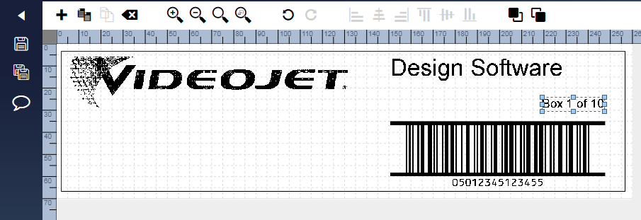
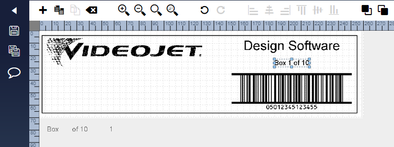
| 15. | To complete the design of the job add two text fields above the ITF barcode. The upper most text field should have the default text of Design Software in Arial 30 point (fonts are changed via the Font tab on the field properties window) and the lower text field should state Box 1 of 10 in Arial 16 point. The image should look something like the following screen shot. |
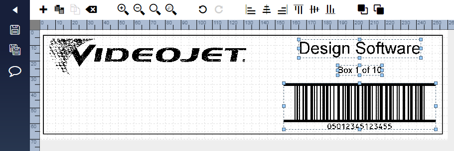
| 16. | Click on the text field Design Software to select it and then hold the Shift key on the keyboard whilst clicking on the text Box 1 of 10 and the ITF Barcode. This selects all three objects. |
| 17. | Click on the Horizontal Centre on the toolbar. This aligns the centre points of all three objects. Drag the objects up /down to ensure a unified 5mm gap between each object. The image will now look like: |
| 18. | Click Save to save the job to the application. |
Advanced Job with Merged Counter Field
This example extends the functionality and flexibility of the job file created in the previous example. The field stating Box 1 of 10 is altered so that the box number automatically increases by one with each print.
This is performed by building up a text field variant called a Merged Field that consists of three other non-printed fields concatenated together: two text fields and the counter field.
A reminder of how the final image will look.

Prepare the job file
| 1. | Locate and open the job file created in the previous example (‘Secondary with Logo’). |
| 2. | Save the file under a new name (‘Secondary with Logo and Counter’) using the Save As functionality. |
Create the Supporting Text Fields
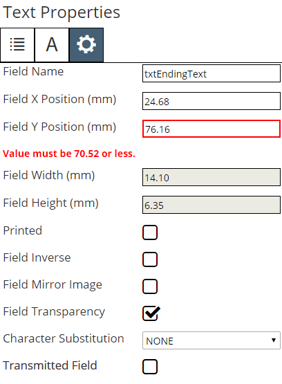
| 3. | Click on the Text tool in the toolbox and give this field a friendly name of ‘txtBeginningText’. Move the text field to the background area. As this text is not printed but used instead within another printed field, it is OK, and normal practice, to place this off the image design area. The date should read ‘Box ’ (note the trailing space). Disable the Printed option on the general tab. Note that the field is now be grey in colour to indicate a non-printed field. |
Repeat the steps in point three above to create another text field called txtEndingText that has the default text of ‘ of 10’ (note the leading space) that is also non-printed. The two fields Properties windows should look as follows:
Add a Counter Field
| 4. | A counter field instructs the printer to increment a numeric / alpha / alpha-numeric field by a certain amount at each print. It is the printer that manages the incrementing – the message is not downloaded for each print. |
Click on the Counter tool in the toolbox and give a friendly field name of ‘cntBoxNo’. Move the counter field next to the two supporting text fields created in the previous step.
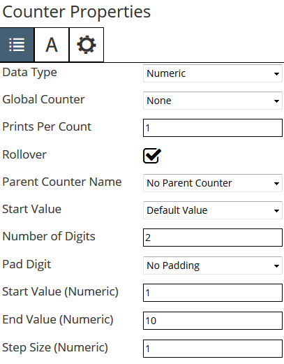
| 5. | Ensure Numeric is selected from the Data Type drop down list on the Counter Properties window. This tells the printer to print and increment a numeric field. |
| 6. | Set the Number of Digits to 2 (as the largest number that is printed is ‘10’). |
| 7. | Select the No Padding option from the Pad Digit drop down list as we do not want the number printed as ‘01’ or ‘ 1’. |
| 8. | Set the Start Value (Numeric) to 1 and End Value (Numeric) to 10 as we do not want to print a figure above 10 (the maximum number of boxes). The Step Size should be set to ‘1’ to tell the printer to increment the number by one at each print. The Numeric tab of the Counter Properties window should now look like: |
| 9. | Set the font to 16 point and on the General tab, disable the option Printed. |
Create a Merge Field
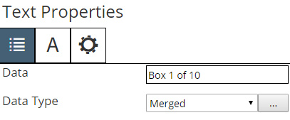
| 10. | To ensure the label is printed as clearly and professionally as possible with correct character spacing, now build a ‘Merge Field’ consisting of the beginning text, counter, and ending text concatenated together. Double click on the text field Box 1 of 10 to display its properties window if window not opened. |
| 11. | The Type drop down list is currently set to Fixed Text (the default). Change this to Merged by selecting this option from the list. A new button appears beside the Data Type drop down. |
| 12. | Click ... to display the Merge Field Properties. |

| 13. | A list of available fields that can be merged appear in the list (a good example of why friendly field names are so important). Select and add the fields that need to be merged so that they appear in the list. The sequence in which they are concatenated can be altered by selecting and dragging the required fields. |
Add the txtBeginningText, cntBoxNo and txtEndingText to the selected fields list box and sequence them so that the Merge Field Properties looks as follows.
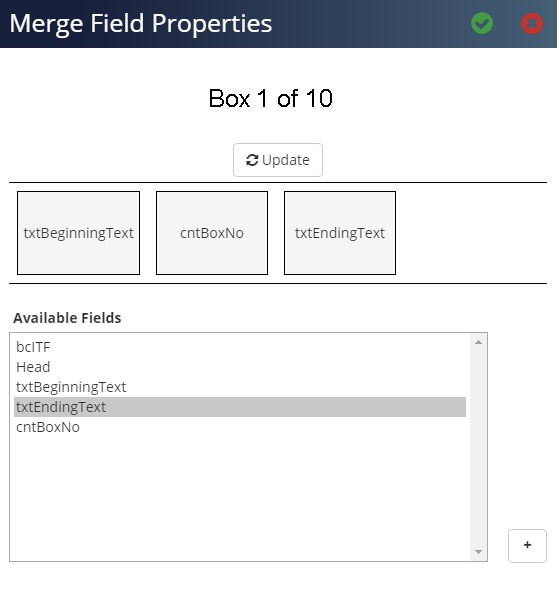
Click ✓ to close the Merge Field Properties window.
| 14. | The job file is now completed. At every print, the merge field displays the correct box number based on the Non-Printed counter field. |
| 15. | Click Save to save the job file. |